INITIAL SET-UP AND OPERATION
3.1 OPERATOR’S SAFETY PRECAUTIONS
SAFE OPERATION IS NO ACCIDENT; observe these rules:
- Know the machine. Read and understand the Operating Instructions.
- Notice all warning labels on the machine.
- Wear proper clothing. Avoid loose fitting garments, and remove watches, rings or jewelry that could cause a serious accident.
- Maintain a clean work area. Avoid accidents by cleaning up the area and keeping it clean.
- Stay alert at all times. Know which switch, push button or control you are about to use and what effect it is going to have.
- Disconnect power for maintenance. Never attempt to repair or perform maintenance on the machine until the main electrical power has been disconnected.
- Do not operate under unsafe operating conditions. Never operate the machine if unusual or excessive noise or vibration occurs.
3.2 OPERATING CONTROLS AND INDICATORS
Before operating the machine, it is required that the operator know the function of each operating control. Refer to Figure 3-1 for the location of the operating controls on the machine. For the information regarding error codes displayed on the control panel, refer to the troubleshooting section of this manual.
A. INTELLITEC2 TOUCHPAD
WARNING
High voltage will shock, burn or cause death. The OFF-ON switch must be placed in the OFF position prior to disassembling for cleaning or servicing. Do not operate machine with panels removed.
Main Power On/Off
The Main Power button is used to supply power to the IntelliTec2™ control, the freezing cylinder circuits and the storage refrigeration system. When the machine is first plugged in, the control defaults to the On status with power to the hopper only. If the Main Power On/Off button is pressed when the machine is on, the machine turns off and a status message displays on the screen.
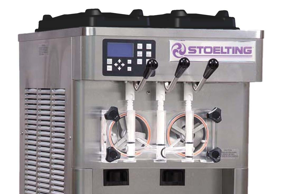
(See Figure 3-2)
Figure 3-1 Machine Controls
F231 IntelliTec2 Control Board:

| Button/Switch | Description |
|---|---|
| Help | Pressing the Help button displays help information dependent on the cursor's location. Pressing the Help button again exits the help screen. |
| Selection Button (SEL) | The SEL button is used by technicians to select menu options. |
| Set Button (SET) | The SET button is used by technicians to save changes when modifying control settings. |
| On/Off Button | Power to the freezing cylinders is controlled with the On/Off Left and On/Off Right switches. |
| Push to Freeze Button | Pressing the PUSH TO FREEZE button initiates "Serve Mode". |
| Clean Button | The CLEAN button initiates "Clean Mode". |
| Arrow Buttons (⬅, ➡, ⬆, ⬇) | The arrow buttons are used by technicians to navigate through the control readings and settings. |
Additional F231 Stoelting Controls:
| B. SPIGOT SWITCH | The spigot switch is mounted to the spigot cam assembly behind the header panel. When the spigot is opened to dispense product, the spigot switch opens and the “Serve Mode” begins. |
| C. DISPENSE RATE ADJUSTOR | The dispense rate adjustor is located under the header panel, to the immediate right of the spigot handles. Turning the knob counterclockwise will decrease the dispense rate. |
| D. MIX LOW LIGHTS | The mix low lights are located at the back of the F231. There is a light for each freezing cylinder. A steady light signifies a low mix condition. A blinking light signifies an error. The light will automatically turn off when the condition has been resolved. |
| E. USB ACCESS PORT | The USB access port is located on the right side panel of the machine. The port is used by technicians to import firmware and export machine statistics. |
3.3 DISASSEMBLY OF MACHINE PARTS
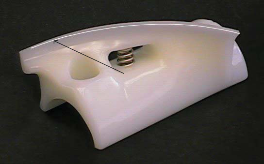
Before using the machine for the first time, complete machine disassembly, cleaning, and sanitizing procedures need to be followed. Routine cleaning intervals and procedures must comply with the local and state health regulations. Inspection for worn or broken parts should be made at every disassembly of the machine. All worn or broken parts should be replaced to ensure safety to both the operator and the customer and to maintain good machine performance and a quality product. Check the wear line on the auger flights on a regular basis (Fig. 3-3) and replace as needed.
To disassemble the machine, refer to the following steps:
A. Removing Mix
For the first time cleaning the machine, skip to part B.
NOTE: If the water does not drain clear, repeat steps 2-4.
- Press the Clean button. After mix has melted (about 5 minutes) open the spigot to drain the mix.
- Fill the hopper with 2 gallons (8 liters) of cool tap water.
- Press the Clean button to run the machine. After 30 seconds press the Clean button again to stop the auger.
- Drain the water out of the machine.
- Use Stera-Sheen or equivalent sanitizing solution mixed according to manufacturer’s instructions to provide a 100 parts per million strength solution. Mix sanitizer in quantities of no less than 2 gallons of 90° to 110°F (32°C to 43°C) water. Any sanitizer must be used only in accordance with the manufacturer’s instructions.
- Pour the sanitizer into the hopper.
- Using brushes provided, scrub the hopper.
- After 5 minutes, drain the sanitizer out of the freezing cylinder.
B. Disassembly of Front Door:
- Turn the machine off by pressing the Main Freezer Power Off/On button on the IntelliTec2 control.
- Remove the knobs on the front door.
- Remove the front door by pulling it off the studs.
- Remove the spigot through the bottom of the front door.
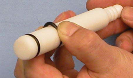
- Remove all o-rings from parts by first wiping off the lubrication using a clean towel. Then squeeze the o-ring upward to form a loop (Fig. 3-4). Roll the o-ring out of the groove
B. DISASSEMBLY OF AUGER
- Remove the front auger supports and bushings.
- Remove the auger assemblies from the machine. Pull the augers out of the freezing cylinders slowly. As the augers are being pulled out, carefully remove each of the plastic flights with springs.
- Keep the rear of the augers tipped up once they are clear of the freezing cylinders to prevent the rear seal assemblies from dropping.
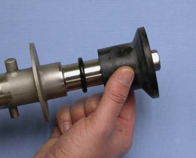
- Wipe the lubricant off of the hex ends of the augers with a paper towel. Remove the rear seal assemblies (Fig. 3-5).
- Unscrew the springs from the auger flights.
3.5 CLEANING DISASSEMBLED PARTS
Disassembled parts require complete cleaning, sanitizing and air drying before assembling. Local and state health codes dictate the procedure required. Some state health codes require a four sink process (pre-wash, wash, rinse, sanitize, air dry), while others require a three sink process (without the pre-wash step). The following procedures are a general guideline only. Consult your local and state health codes for the procedures required in your location.
- Disassemble all parts. (Refer to Section 3.4 for the disassembly of machine parts)
- Place all parts in 90° to 110°F (32°C to 43°C) mild detergent water and wash thoroughly. Use the brushes that shipped with the machine to clean all holes in the front door, flights, mix pickup assembly, etc.
- Rinse all parts with clean 90° to 110°F (32°C to 43°C) water.
- Place all parts in a sanitizing solution for at least 1 minute, then remove and let air dry completely before assembling in machine.
3.5 SANITIZING MACHINE PARTS
- Use Stera-Sheen or equivalent sanitizing solution mixed according to manufacturer’s instructions to provide a 100 parts per million strength solution. Mix sanitizer in quantities of no less than 2 gallons of 90° to 110°F (32°C to 43°C) water. Any sanitizer must be used only in accordance with the manufacturer’s instructions.
- Place all parts in the sanitizing solution for 5 minutes, then remove and let air dry completely before assembling in machine.
3.6 CLEANING THE MACHINE
The exterior should be kept clean at all times to preserve the luster of the stainless steel. A high grade of stainless steel has been used on the machine to ease cleanup. To remove spilled or dried mix, wash the exterior with 90° to 110°F (32°C to 43°C) Stera-Sheen solution or equivalent cleaner and wipe dry.
Do not use highly abrasive materials, as they will mar the finish. Use a soft cloth or sponge to apply the solution. For best results, wipe with the grain of the steel
Note: Do not let sanitizing solution sit overnight in the freezing cylinder.
- Clean the rear seal surface from inside of the freezing cylinder.
- Using sanitizing solution and the large barrel brush provided, sanitize the freezing cylinder by dipping the brush in the sanitizing solution and brushing the inside of the freezing cylinder.
- Remove the drip tray by pulling from the front panel. Clean and replace the drip tray.
3.7 ASSEMBLING MACHINE
To assemble the machine parts, refer to the following steps:
NOTICE
Total Blend sanitary lubricant, Petrol-Gel sanitary lubricant, or equivalent must be used when lubrication of machine parts is specified.
Total Blend can be used in place of two products. It is used to lubricate parts and also used in place of spline lubricant. Do not use more than one packet of Total Blend per freezing cylinder.
NOTICE
The United States Department of Agriculture and the Food and Drug Administration require that lubricants used on food processing equipment be certified for this use. Use lubricants only in accordance with the manufacturer’s instructions.
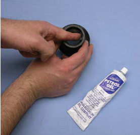
- Assemble all o-rings onto parts dry, without lubrication. Then apply a thin film of sanitary lubricant to exposed surfaces of the o-rings.
- Install the rear seal o-rings onto the augers. Lubricate the outside of the o-rings with auger lubricant Total Blend lubricant.
- Lubricate the inside metal surface of the rear seals (Fig. 3-6) and install them onto the auger shafts. DO NOT lubricate the outside of the rear auger seals.
- Lubricate the hex drive end of the auger with a small amount of spline lubricant. A small container of spline lubricant is shipped with the machine.
- Screw the springs onto the studs in the plastic flights. The springs must be screwed into the flights completely to provide proper compression.
6. Install the two plastic flights onto the rear of the auger and insert it part way into the freezing cylinder.
7. Install the remaining plastic flights, push the auger into the freezing cylinder and rotate slowly until the auger engages the drive shaft.
8. Apply a thin layer of sanitary lubricant to the inside and outside of the auger support bushing. Install the bushing onto the auger support and install the auger support into the front of the auger. Rotate the auger support so that one leg of the support points straight up.
9. Apply a thin layer of sanitary lubricant to the o-rings on the spigot body and install the spigot body through the bottom of the front door.
10. Apply a thin film of sanitary lubricant to the door seal o-ring and fit it into the groove on the rear of the front door.
11. Place the front door assembly on the mounting studs and push the front door against the machine carefully.
12. Secure the front door to the machine by placing the knobs on the studs and tightening until finger tight. Do not overtighten. A proper o-ring seal can be observed through the transparent front door.
3.8 SANITIZING
Sanitizing must be done after the machine is clean and just before the machine is filled with mix. Sanitizing the night before does not ensure sanitization the next day. However, you should always clean the machine and parts after using it.
NOTE
The United States Department of Agriculture and the Food and Drug Administration require that all cleaning and sanitizing solutions used with food processing equipment be certified for this use.
When sanitizing the machine, refer to local sanitary regu- lations for applicable codes and recommended sanitizing products and procedures. The frequency of sanitizing must comply with local health regulations. Mix sanitizer according to manufacturer’s instructions to provide a 100 parts per million strength solution. Mix sanitizer in quanti- ties of no less than 2 gallons of 90°F to 110°F (32°C to 43°C) water. Allow sanitizer to contact the surfaces to be sanitized for 5 minutes. Any sanitizer must be used only in accordance with the manufacturer’s instructions.
- Prepare 2 gallons of Stera-Sheen sanitizing solution following the manufacturer’s instructions.
- Install the mix inlet regulator into the hopper.
- Pour the sanitizing solution into the hopper.
- Make sure the display shows the freezing cylinder is off. If it is not, press the On/Off Left or On/Off Right button to turn it off.
- Press the CLEAN button.
- Check for leaks.
I. Check for leaks at the front door seals.
II. Check the drain tray located under the front door for leaks coming from the rear of the rear auger seal. - Using a sanitized soft bristle brush (or equivalent) dipped in sanitizing solution, clean the hopper sides, mix inlet regulator, and underside of the hopper cover.
- After five minutes, open the spigot to expel sanitizing solution. Drain all of the solution from the machine.
- When the solution has drained, press the CLEAN button to stop the auger. Allow the freezing cylinder to drain completely.
The machine is now sanitized and ready for adding mix.
3.9 FREEZE DOWN AND OPERATION
- Sanitize immediately before use.
- Make sure the display shows the freezing cylinder is off. If it is not, press the On/Off Left or On/Off Right button to turn it off.
- Fill the hopper with at least 2.5 gallons of mix.
- Place a container under the spigot and open the spigot to allow the mix to flush out about 8 ounces (0.23 liters) of sanitizing solution and liquid mix.
- Press the On/Off button for the cylinder.
- Press the PUSH TO FREEZE button.
- When the product is at 75% consistency, the display will read "SERVE". Open the spigot to dispense product.
- The machine dispenses product at a reasonable draw rate. If the machine is overdrawn, the result is a soft product or a product that will not dispense at all. If this occurs, allow the machine to run for approximately 30 seconds before dispensing more product. A dispense rate adjustor is located under the header panel, to the immediate right of the spigot handle. Turning the knob counterclockwise will decrease the dispense rate.
- Do not operate the machine when the MIX LOW message is displayed. Refill the mix container immediately.
3.10 FINE CONSISTENCY ADJUSTMENT
If the product consistency needs to be adjusted, use the Fine Consistency Adjustment. To access the setting, the Associate level password must be entered. Follow the steps below for the Fine Consistency Adjustment.
- Press the left arrow from the Current Status screen.
- Press the right arrow then the SEL button from the Password screen. After the password is accepted, move the cursor to the Fine Consistency Adjustment option and press the SEL button.
- On the Fine Consistency Adjustment screen, press the SEL button and use the arrows to modify the setting. Adjust the Fine Consistency higher to increase the consistency or lower to decrease the consistency.
- Press the SET button to save the changes. Make adjustments in increments of 5 for best results.
3.11 MIX INFORMATION
Mix can vary considerably from one manufacturer to another. Differences in the amount of butterfat content and quantity and quality of other ingredients have a direct bearing on the finished frozen product. A change in machine performance that cannot be explained by a technical problem may be related to the mix.
Proper product serving temperature varies from one manufacturer’s mix to another. Mixes should provide a satisfactory product in the 20°F to 24°F range. Diet and low-carb mixes typically freeze to proper consistency at higher temperatures.
When checking the temperature, stir the thermometer in the frozen product to get an accurate reading.
Old mix, or mix that has been stored at too high a temperature, can result in a finished product that is unsatisfactory. To retard bacteria growth in dairy based mixes, the best storage temperature range is between 33° to 38°F (0.5° to 3.3° C).


