
The purpose of this program is to show you the correct opening, operating and closing procedures for the Taylor Model 339/754 soft serve, gravity fed freezers. The 339/754 is a twist master model, which allows you a choice of two separate flavors from the outer spouts or an equal combination of both from the center one. For all practical purposes, the procedures covered in this program will apply to many models of similar nature. Some being counter and counsel versions. Your operator’s manual will explain the individual model differences.
The procedures followed in this training program are those found in your tailor operator's manual. Keep the manual close by as a resource guide. These procedures are important and must be followed accurately to ensure the correct operation of your freezer.
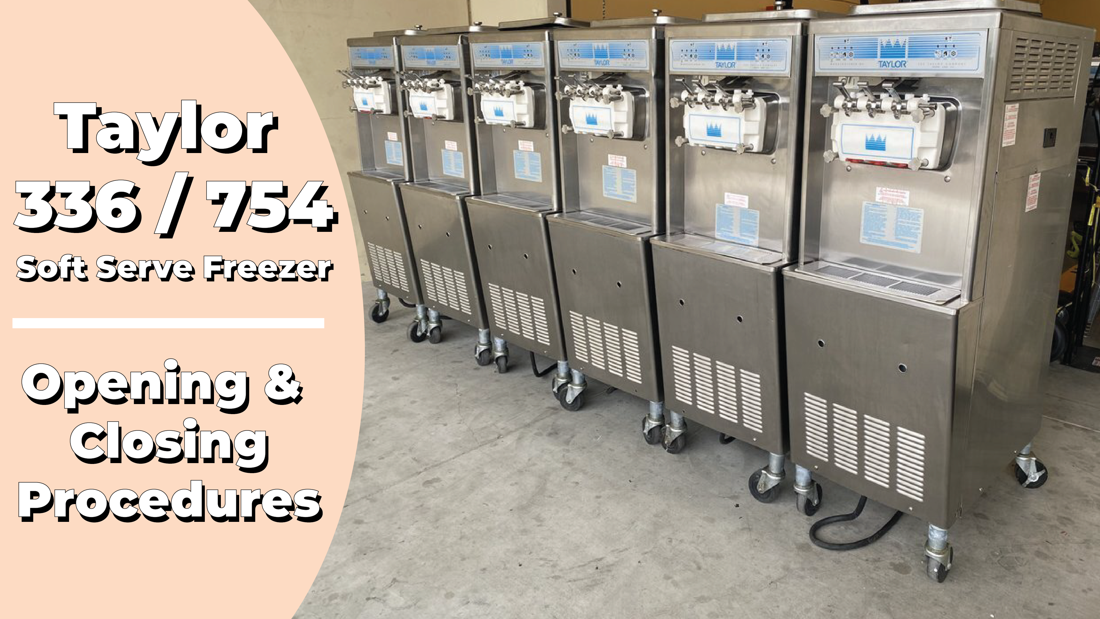
| 336 - Soft Serve Freezer | Spec Sheet | Manual |
| 754 - Soft Serve Freezer | Spec Sheet | Manual |
The 754 has two freezing cylinders of 3.4 quarts, 3.2-liter capacity. The 339 has two freezing cylinders of 2.8 quart, 2.7 liter capacity.
Both models have mixed Hoppers of 20 quart, 18.9 liter capacity. We start your tailor training where you have entered the store in the morning and find the parts disassembled and laid out for air drying from the previous night's cleaning. Opening procedures will show you how to assemble the parts into the freezer, sanitize them and prime the freezer with fresh mix prior to serving product. Let's review the disassembled parts from your freezer:
-
Air-mixed feed tube:
It's hollow with a Port opening at only one end. The air tube regulates the combination of air and mix that enters the freezing cylinder. -
Air Orifice:
restricts the amount of air entering the freezing cylinder. The number of this orifice may differ depending on various products. The standard size is number A 100. -
Beater Assembly:
It blends air and mix while turning inside the freezing cylinder and also ejects product from the cylinder. Depending on the age of your freezer, the beater design may differ. -
Scraper Blades:
They scrape frozen product off the inside wall of the freezing cylinder. The blades can be made of plastic for the new design or metal for the old design -
Drive Shaft:
Is used to rotate the beater assembly -
Freezer Door Assembly:
Covers the open end of the freezing cylinder and provides a dispensing port for the frozen mix. -
Hand Screws:
Secure the door into position. -
Adjustable Draw Handle:
The handle operates the draw valve, which starts or stops the flow of the product. -
Pivot Pin:
Used to secure the draw handles to the freezer door -
Design Cap:
They fit over the bottom of the freezer door spout and provide a star design to the product. -
Prime Plugs:
When raised during priming, they allow undesired air to escape from the freezing cylinders and gives a visual indication when the cylinder is properly primed. -
O-rings:
Used to seal various freezer parts.They need to be lubricated to provide an adequate seal.
CLICK HERE to view a photo gallery of all the Taylor 336 Soft Serve Machine parts, disassembled.
Looking for a USED Taylor 336? We have single and multi-machine packages for the Taylor 336-33! View them below:


Used Equipment Guarantee: We guarantee working condition of our used equipment, or we pay to fix it. No small print hard to read warranty. All shipments are fully insured for damage. SHOP TODAY
Anyways, back to the Taylor 336 Assembly procedures. You'll also need an approved lubricant for moving parts and o-rings. o-rings, gaskets, seals, and the like are wear items that need to be replaced on a 3 month maintenance schedule. A tuneup kit containing all the necessary replacement parts is available from your tailored distributor. Before starting the morning opening procedures, first sanitize your hands in an approved solution.
Taylor 336 Soft Serve Machine Assembly
Begin by lubricating the groove and shaft portion of the drive shaft. Slide the seal over the shaft and groove until it snaps into place. Next, fill the inside portion of the seal with lubricant and the flat side of the seal. Do not lubricate the Hex end of the drive shaft. Now insert the drive shaft into the rear shell bearing and engage the Hex end firmly into the coupling.
Assemble the beater assembly by slipping one end of the scraper blade under the hook at the front end. Now wrap the blade around the Helix and slip the end under the rear hook. Repeat for the second blade. Slide the beater part way into the freezing cylinder and while looking into the cylinder, align the hole at the end of the beater with the flats on the end of the drive shaft. Then complete the installation.
Install the remaining beater assembly, following the same procedure. For proper scraping, there should be a snug fit of the blades to the freezing cylinder. If not, contact your tailored distributor. Should your freezer have metal scraper blades, check the blades for nics or signs of wear. Replace if necessary, and be careful.
These blades are sharp. Prepare the beater assembly by placing the rear blade over the two rear holding pins. Assure the blade is over both pins. Hold the rear blade onto the beater and slide the assembly into the freezing cylinder halfway. Then install the front blade over the front holding pins and complete the installation.
Repeat this procedure for the remaining side. Assemble the freezer door by sliding the gasket over the baffle Rod and into the grooves on the back side of the door. Note that the gasket has a knife edge and a round edge. The round edge is against the door. Assemble the front plastic bearing over the baffle and position so that the flanged edge is against the back of the door.
Some units may require a smaller bearing to be used with the older beater design. Assemble in the same manner. Repeat this procedure for the other side of the door. Do not lubricate the gasket or the front bearing. Next, slide the two orings into the grooves on the prime plug and evenly lubricate.
Repeat for the other prime plug, then insert the prime plugs into the holes atop the freezer door and push down. Install the freezer door by inserting the baffles into the beater openings and position the door flush with the freezing cylinder. Next, install the hand screws long ones on top, short ones on bottom, then tighten, using a crisscross pattern to get a snug fit. Ready the three draw valves by sliding the two orings into the grooves on each valve and lubricate, then lubricate the
freezer door spouts from the top and the bottom.
Insert the draw valves from the bottom up until the slotted opening of the valve comes into view. Now slide the Oring into the groove on the pivot pin and lubricate. Align the end of the draw handles into the slots of the draw valves, then slide the pivot pin through each handle. Snap the design caps over the bottom of the freezer door spouts. Slide two orings onto each end of the air tube, then slide the Oring into the groove of the air orifice. Do not lubricate.
Check that the hole in the orifice is clean. Then install the orifice into the air tube end without the port opening. Assemble the remaining air tube and orifice in the same manner. Lay the air tube assemblies and Hopper gasket in the bottom of the mix Hopper prior to cleaning and sanitizing. Install the front drip tray and splash shield, then slide the rear drip tray into the opening on the side panel.
Taylor 336 Soft Serve Freezer: Sanitizing
For sanitizing, you'll need a two gallon 7.6 liter pale brushes and an approved cleaning sanitizing agent. These items are to be stored properly and used only for the freezer. Mix 2 gallons, (7.6 liters) of warm water with 100 parts per million cleaning sanitizing agent, according to manufacturers specifications. The agent used here requires just a one step process. The agent used in your area may differ, requiring a two step process; one step cleaning one step for sanitizing. Follow health codes in your area.
Pour the entire amount of solution into one Hopper, allowing it to flow into the cylinder, then thoroughly brush clean the Hopper. Take care to brush clean the mixed level sensing probe located on the rear wall of the Hopper. Then brush cleaned the mix Inlet hole, the air tube assembly, and the Hopper gasket. Now place the power switch to the on position. Press the word wash to cause the solution in the cylinder to be agitated.
Allow to agitate from a minimum of 2 minutes to a maximum of 5 minutes, as this may vary in your local. With the pale beneath the draw spouts, raise the prime plug. When a steady stream of solution flows from the plug opening, pull down the draw valve handle, then momentarily pull down the center draw handle. Draw off all the solution. When the flow stops, raise the draw handle and press wash to Cancel operation. Repeat this cleaning sanitizing sequence for the second freezing cylinder in the exact same manner. Then, with sanitized hands, assemble the Hopper gasket around the top edge of the mix Hoppers. Place the air tube assemblies in the corner of each Hopper. The freezer is now ready to be primed.
Taylor 336 Frozen Yogurt Machine: Priming
To ensure your customers the best quality product, priming the machine as close as possible to the time when the first draw is needed. 30 minutes before the product is needed should be sufficient. With a pale beneath the draw spout, lower the draw handle and with the prime plug in the up position, pour two gallons 7.6 liters of fresh mix into the Hopper, allowing it to force out any solution. When full strength mix is flowing from the draw spout opening, raise the draw handle. When a steady stream of mix flows from the prime plug opening in the door bottom, push down the prime plug.
Install the air tube end with the Port opening into the mix Inlet hole. Now press auto. The auto and mix ref lights come on, indicating that the main refrigeration and mix refrigeration systems are operating. When the unit cycles off, the product is ready to be served. Under normal conditions, this length of time may take approximately 7 minutes. Repeat this procedure for the second freezing cylinder.
Now place the sanitize mix Hopper covers into position. You are now ready to begin drawing product. Start by placing the product on the rim of the cone and with a circular motion, placed the desired number of swirls atop the cone while closing the handle, to achieve the peak effect.
Taylor 336: Disassembly
At the end of each day, the freezer needs to be disassembled. The following items are needed:
- Two Pales
- Stainless Steel Rerun Can with Lid
- Necessary Brushes
- Cleaner
- Sanitizer
- Towels
- Three-Comparment Sink
To drain product from the freezing cylinder, press auto and mix ref. This cancels the beater motor and both main and auxiliary compressors. Remove the Hopper covers, air tubes, and Hopper gasket, and take to the sink for cleaning.
With a sanitized pale beneath the draw spout, press watch. Pull down the draw handle and drain the remaining product from the freezing cylinder and mix Hopper. When all the product stops flowing, raise the draw handle and press wash again. If local health codes permit, empty the rerun into the sanitized stainless steel rerun container. Cover and place in the cooler.
Follow local health codes concerning rerun. Repeat this procedure for the second freezing cylinder. Rinsing. The machine requires pouring two gallons, 7.6 liters of cool clean water into the Hopper. With the brushes, scrub the Hopper, the Inlet hole and a level sensing probe.
Place the pale beneath the draw spot. Raise the prime plug and press wash. When a steady flow of rinse water flows from the plug opening, lower the draw handle, drain all the rinse water from the draw spout then raise the draw handle and press wash, canceling operation.
Continue this rinsing procedure until the rinse water flows clear. Repeat this procedure for the second freezing cylinder. Prepare two gallons, 7.6 liters of cleaning sanitizing solution in warm water. Push down the prime plug and pour the solution into the mix Hopper, allowing it to flow into the cylinder. Brush cleaned the Hopper, the Inlet hole, and the level sensing probe.
Press wash for agitating the solution in the cylinder. With an empty pail beneath the spout raise the prime plug. With a steady stream of solution flowing from the prime plug opening, pull down the draw handle and draw off all the solution. When the solution stops flowing from the draw spoUt, press wash to cancel operation.
Repeat the same cleaning sanitizing procedure for the second freezing cylinder. With the power switch off and no panel lights lit, remove the hand screws, remove the freezer door, the beaters and scraper blades, and the drive shafts. Take these items to the sink for cleaning. Note when using metal blades, be careful not to allow a blade to fall free. Next, remove the front drip tray and splash shield for cleaning.
Now remove the rear drip tray from the side panel for cleaning. A note. If the tray has an excessive amount of mix in it, this may mean the seal on the drive shaft to the beater assembly may need replacing, proper lubrication, or correct installation. Prepare the sinks with a necessary cleaning sanitizing solution in warm water and have all the necessary brushes. Remove the seal from each of the drive shafts from the freezer door.
Remove the gaskets, the front bearings, the pivot pin, the draw handles, the design caps, the draw valves, and the prime flux. At this time, remove all o-rings. Use the towel to grasp the o-ring, apply pressure in an upward direction until the o-ring pops out of the groove. Now push the top of the o-ring forward. It will roll out of the groove and be easily removed.
Never use sharp objects, which may damage the o-ring. At the sink, thoroughly brush clean all the parts in the cleaning sanitizing solution, making sure all lubricant and mixed film is removed. Be sure to brush clean the draw valve cores in the freezer door, place all the sanitized parts on a clean dry surface to air dry overnight. Return to the freezer with some cleaning sanitizing solution and with the black brush. Clean the rear shell bearing at the back of each freezing cylinder.
Now light clean the exterior surfaces of the freezer.
As a crew member, this completes your section of training is most Soft Serve stores! However, if you want more detailed, opertaional instructions usually reserved for managment & owners, read part 2 of this article HERE
Parts Gallery:

Air-Mixed Feed Tube

Air Orifice

Beater Assembly

Scraper Blades

Drive Shaft

Freezer Door Assembly

Hand Screws

O-rings

Adjustable Draw Handle

Pivot Pin

Design Cap

Prime Plugs
TAYLOR 336 INSTALLATION GUIDE: (PART 2)
We will review installation, proper use and important notes to the operator. For your understanding and safety, we strongly urge that you review all sections of the Taylor Operator's manual before using the freezer. Proper installation of your freezer is very important.
Safety codes may vary in some locations and therefore change the specifications covered in this program section. As a safeguard against electrical shock, the freezer must be installed as described in the operator's manual. The freezers data plate describes the needed voltage requirements. The freezer used here requires two separate, 208/230 volts power supplies. Each power supply must have a separate wall receptacle with a 35 amp rating.
A 3 inch, 7.6 centimeter airspace around all four sides of the machine and a floor clearance of 7.5 inches, (19.1 centimeters) are required for correct performance of the freezer. These units feature an adjustable draw handle to provide better portion and cost control. In addition to better product quality. When the product is at the correct viscosity, the draw handle needs adjustment.
It must be adjusted to provide a flow rate of 5 to 7.5 ounces, 142 to 212 grams of product by weight per ten second draw. This is the standard plastic adjusting screw. Metal ones are optional. It is used to regulate the draw rate to match the liquid mix entry into the rear of the freezing cylinder. To increase the flow rate, turn the adjusting screw counterclockwise and clockwise to decrease the flow rate.
The power switch is located under the control channel. When placed in the on position, it allows for SoftTech control panel operation. Let's review the SoftTech control panel:
this is the Mix low indicator light. When flashing, it indicates the mix Hopper has a low supply of mix and needs to be refilled.
There should always be at least three inches (7.6 cm) of mix in the Hopper. Failure to do so may result in a freeze up, causing eventual damage to the beater blades, drive shaft, and freezer door. This is the mix refrigeration control. When this is pressed, the indicator light comes on and the tone sounds indicating that the mix Hopper refrigeration system is operating. This function cannot be cancelled unless the auto or standby are canceled first.
Standard features on the 339 / 754 models are the separate Hopper refrigeration (SHR) and the Cylinder Temperature Retention System (CTR) uses a separate small refrigeration system to chill and maintain Hopper mix to below 40 degrees Fahrenheit, to assure bacterial control. The CTR feature maintains a good quality product during long no sale periods. To do so, it is necessary to warm the product in the freezing cylinder to 40 degrees Fahrenheit, to prevent product over beating and breakdown.
The CTR assures mix in the freezing cylinder is refrigerated during the standby mode of operation. To activate the standby mode of operation, press the word standby. The light comes on and the tone sounds. Then, with sanitized hands, remove the air orifice and lift out the air tube. Turn the tube over and replace the end without the Port into the mix Inlet hole.
Repeat for the other Hopper. To return to normal operation, press auto. When the unit cycles off the product in the freezing cylinder will be at serving viscosity again with sanitized hands, remove the air tube, turn it over and insert the end with the Port into the mix Inlet hole and install the sanitized air orifice repeat for the other Hopper. Should a beater motor overload ever occur, the reset mechanism will trip automatically, shutting down the freezer. This is the reset button on counter models. It's located on the side of the unit.
Here on the Council model is found in the service panel. To properly reset the freezer, press auto. Move the power switch to off, then firmly depress the reset button. Next, turn the power switch to on press wash for both sides and observe the freezers performance. If the freezer is operating properly, press wash, then press auto on both sides to resume normal operation.
Should the freezer shut down again, you'll need to contact the service technician. This concludes your tailor operations training. We hope this program has proven beneficial for your needs